10/12/2018
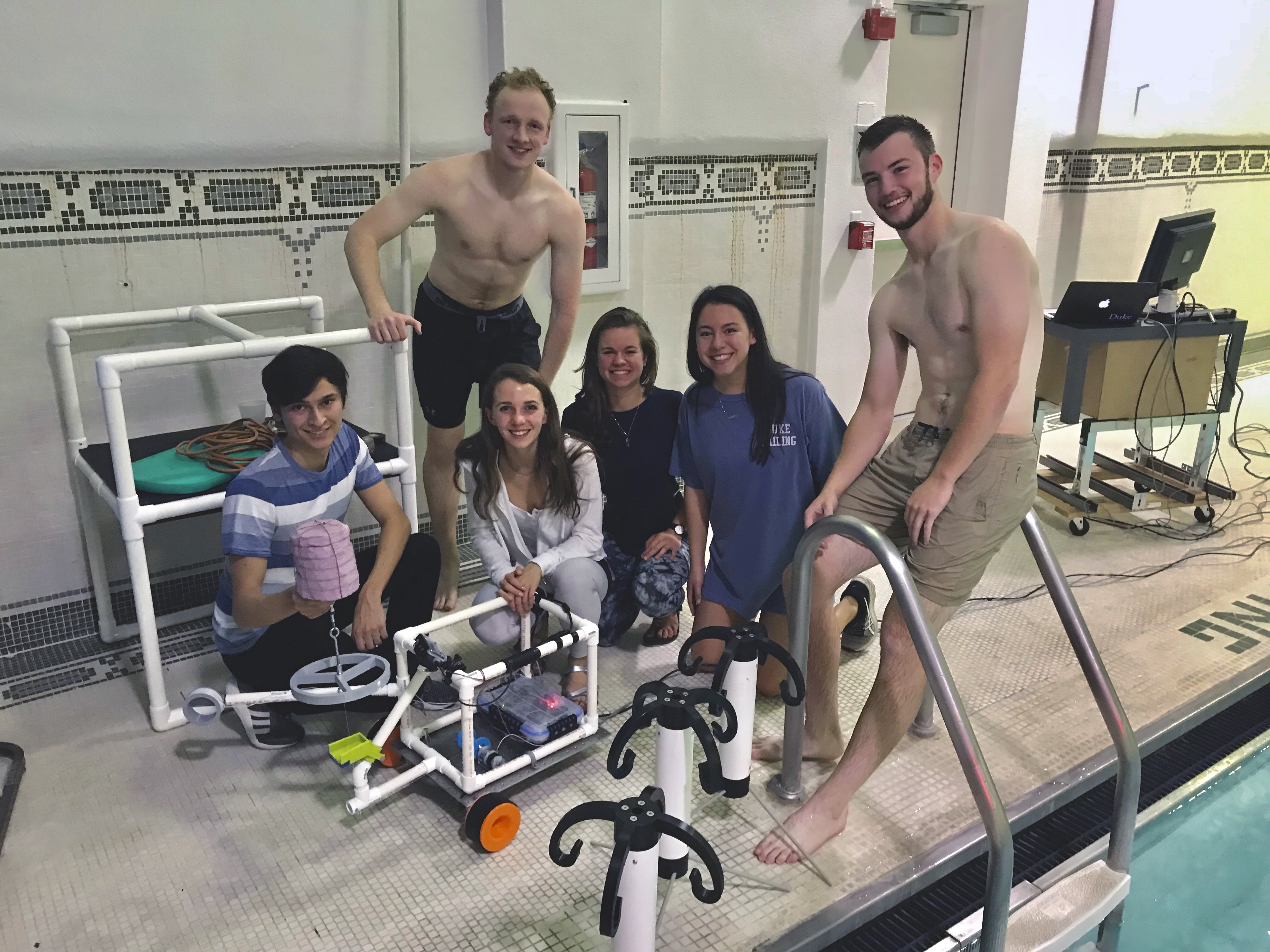
In a team of 6, we were tasked to design, prototype, and test an underwater robot capable of distinguishing and retrieving three objects from the bottom of a pool.
I spearheaded the tread-and-wheel-base design and prototyping. I am also responsible for the for documentation for this project: from sketches, through SolidWorks files, to testing videography.
Some of our initial group-meeting ideas, specifically regarding buoy and frame design:

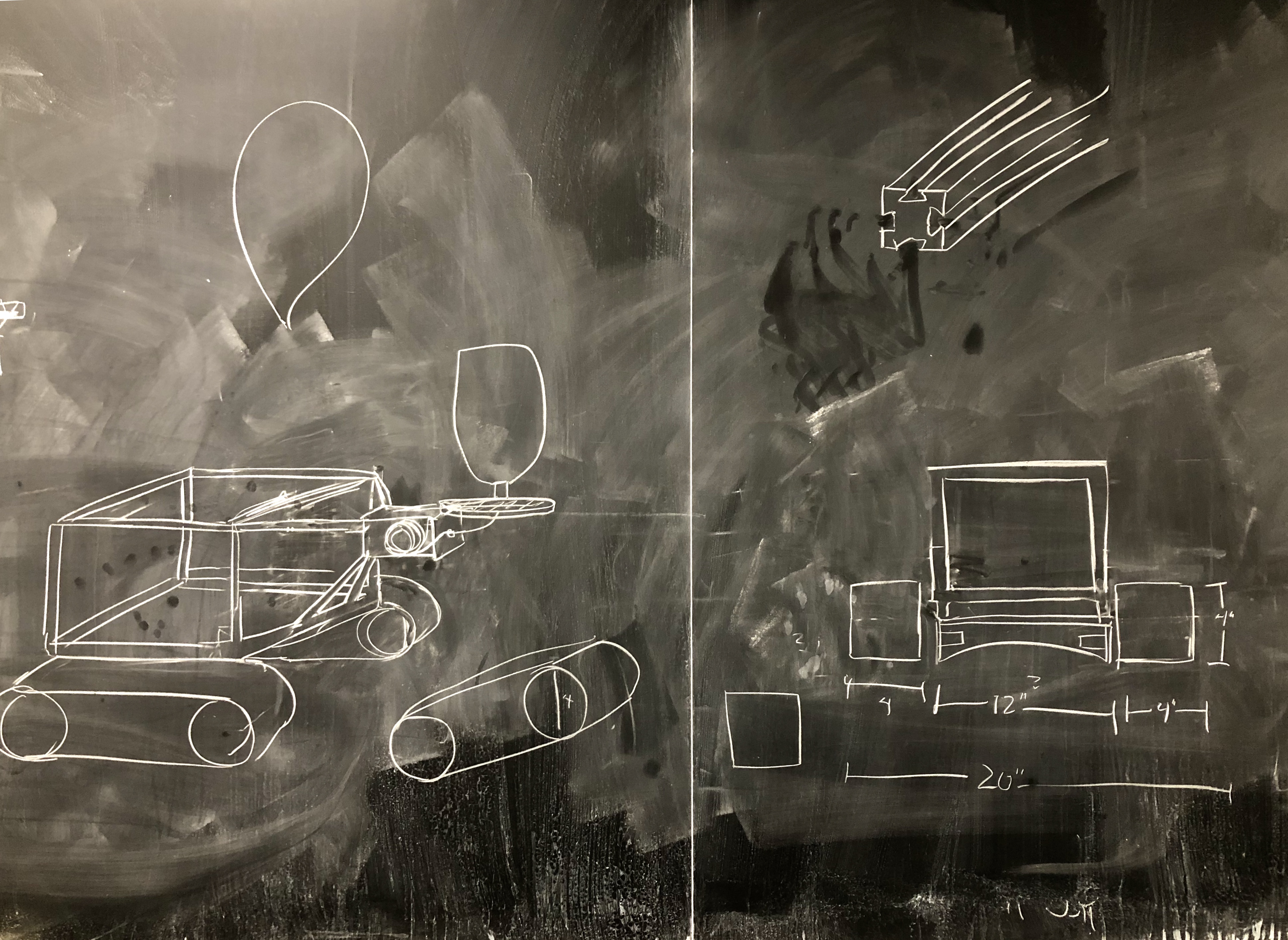
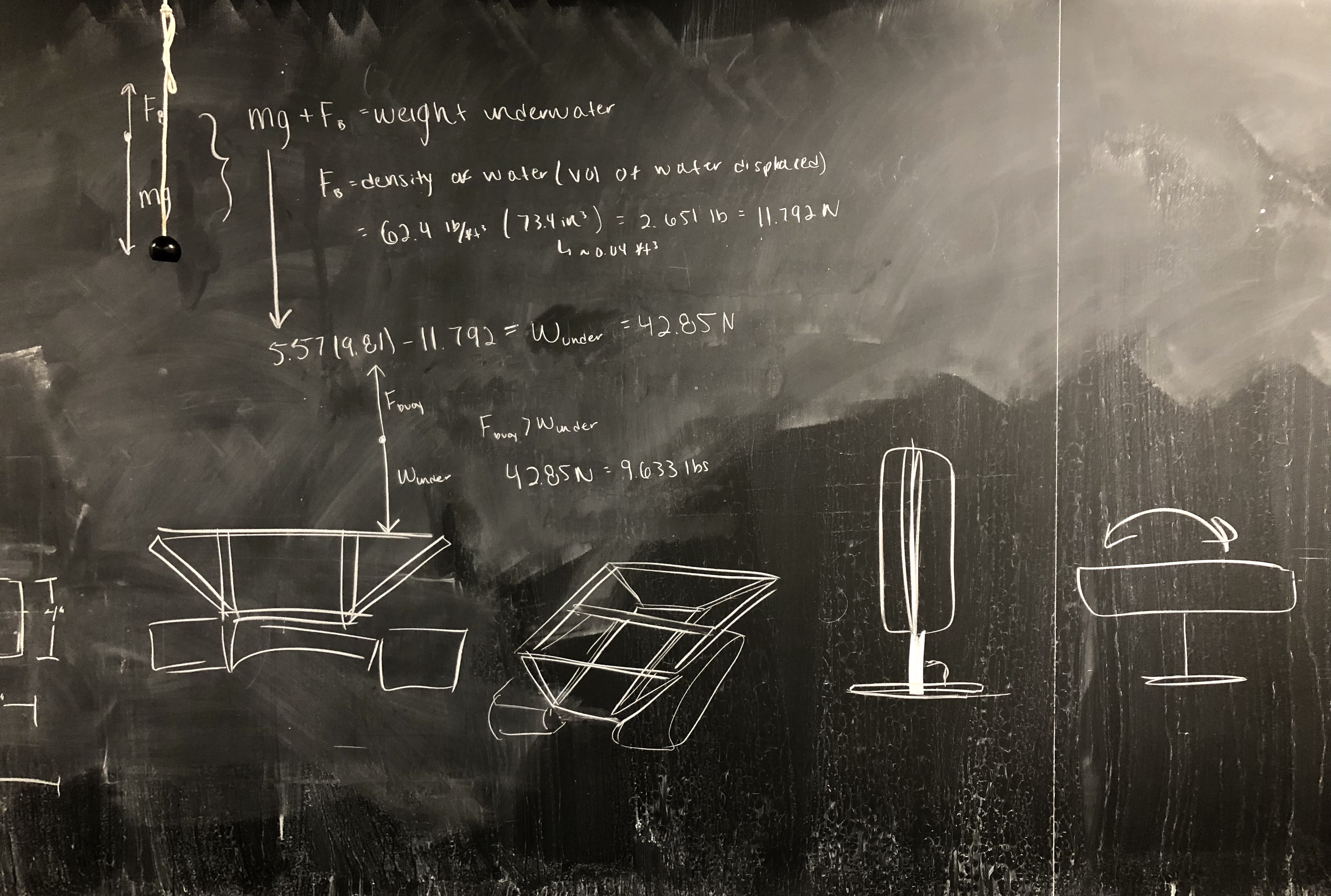
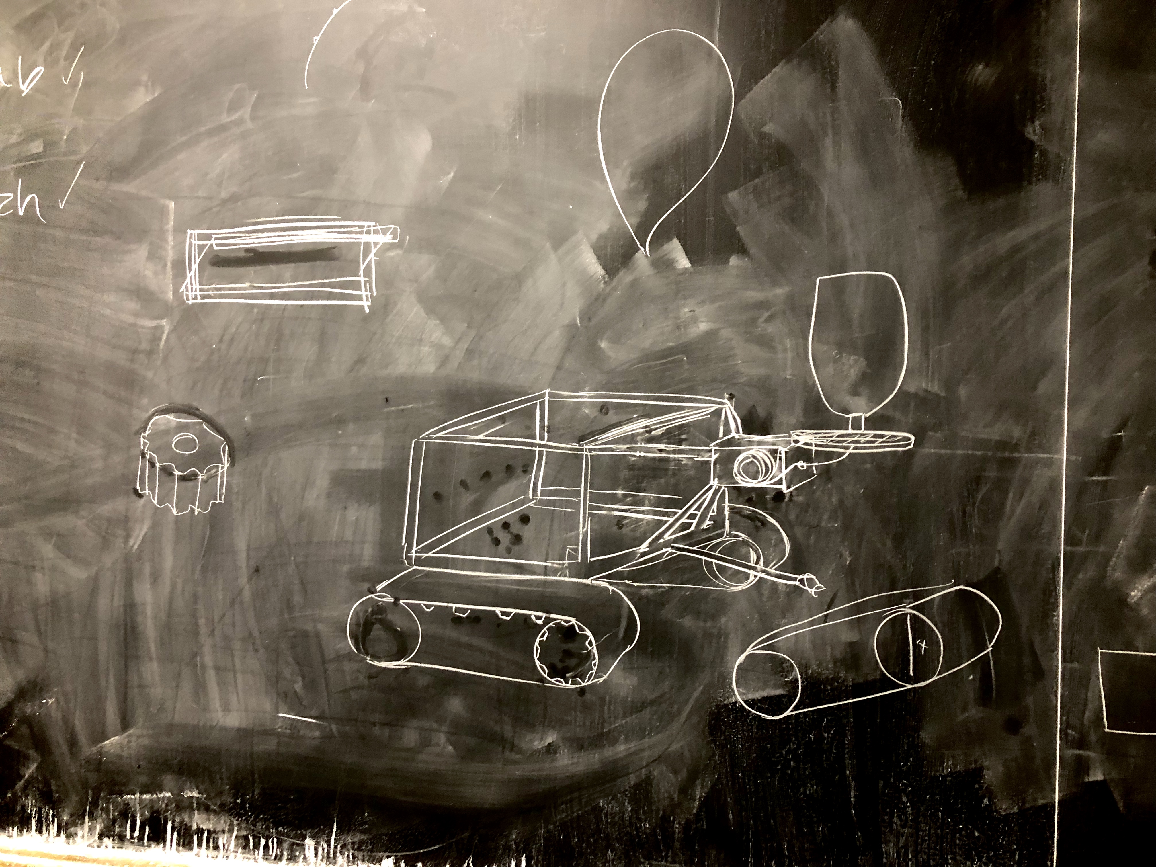
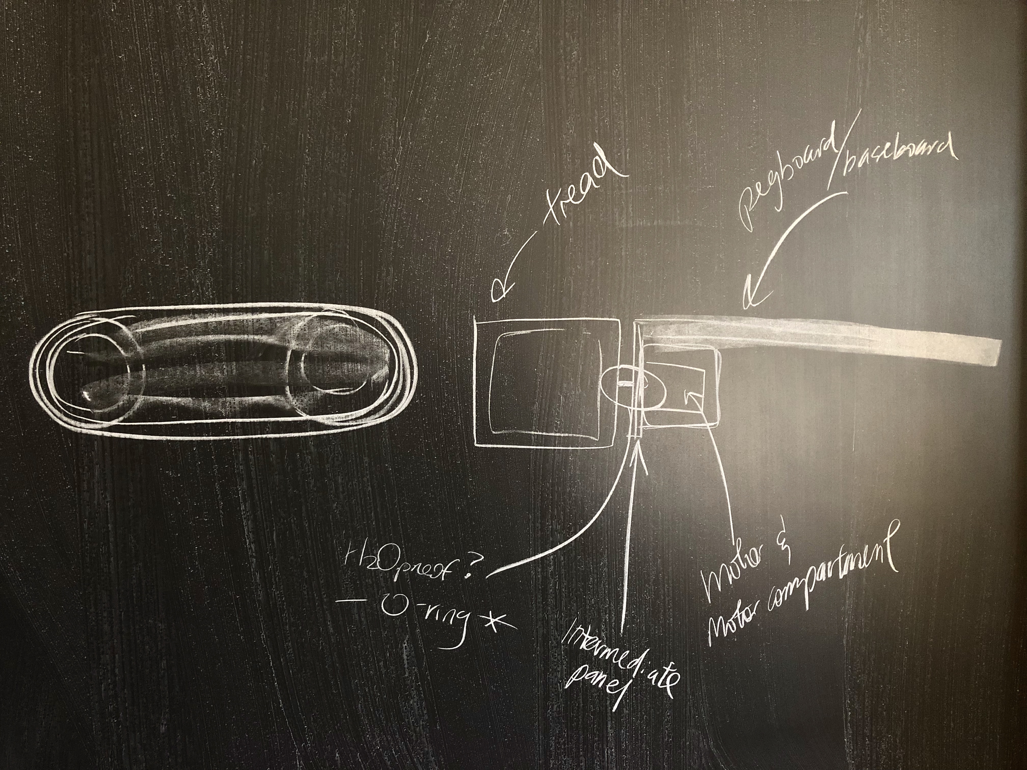
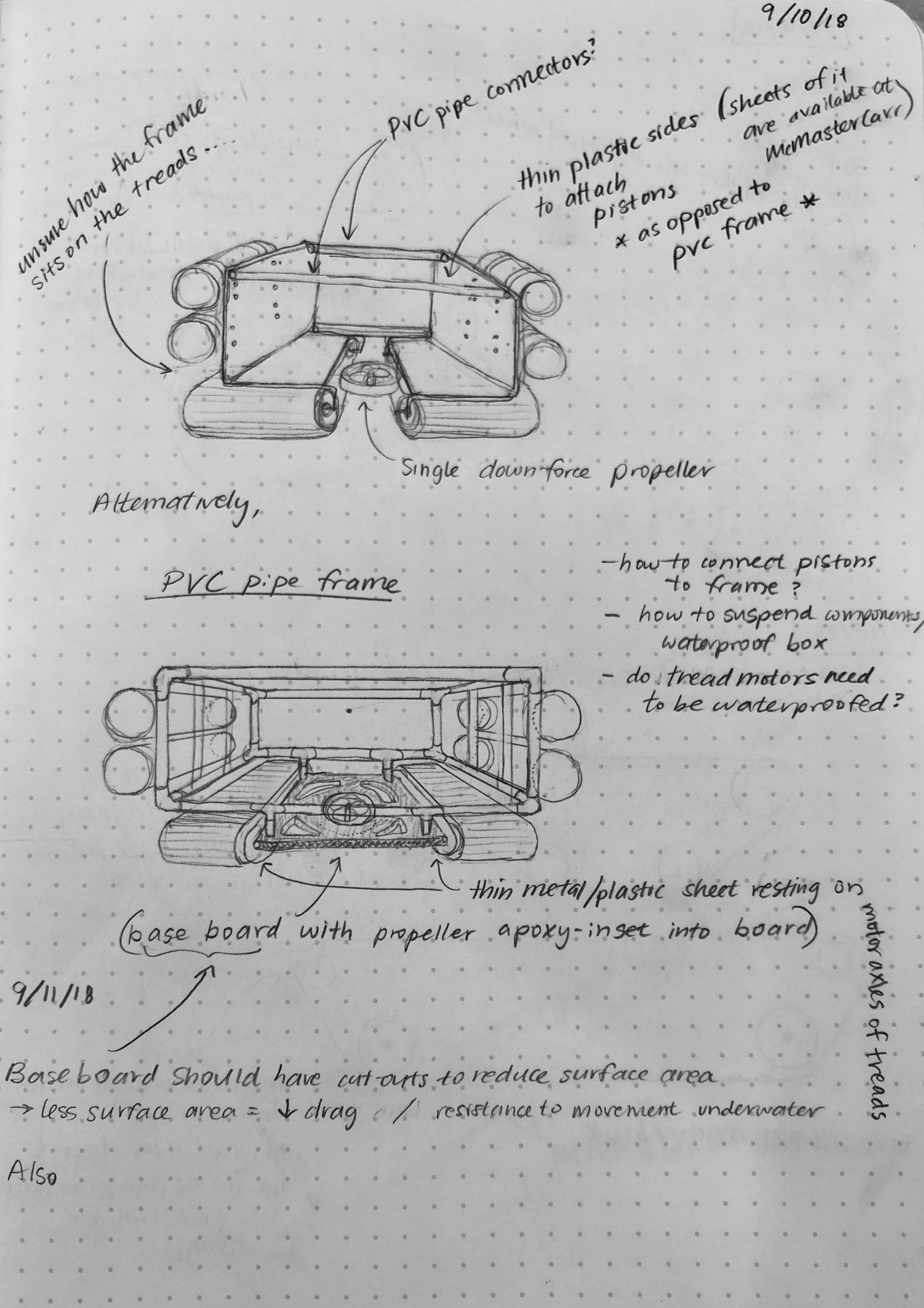
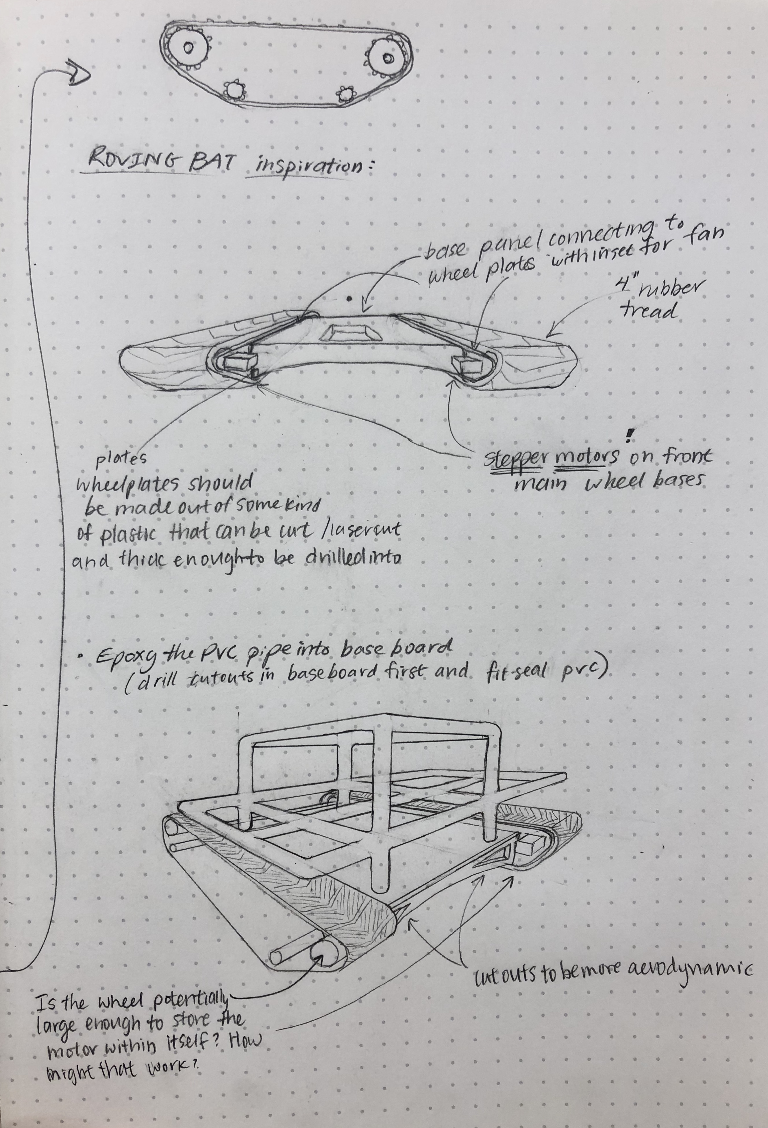
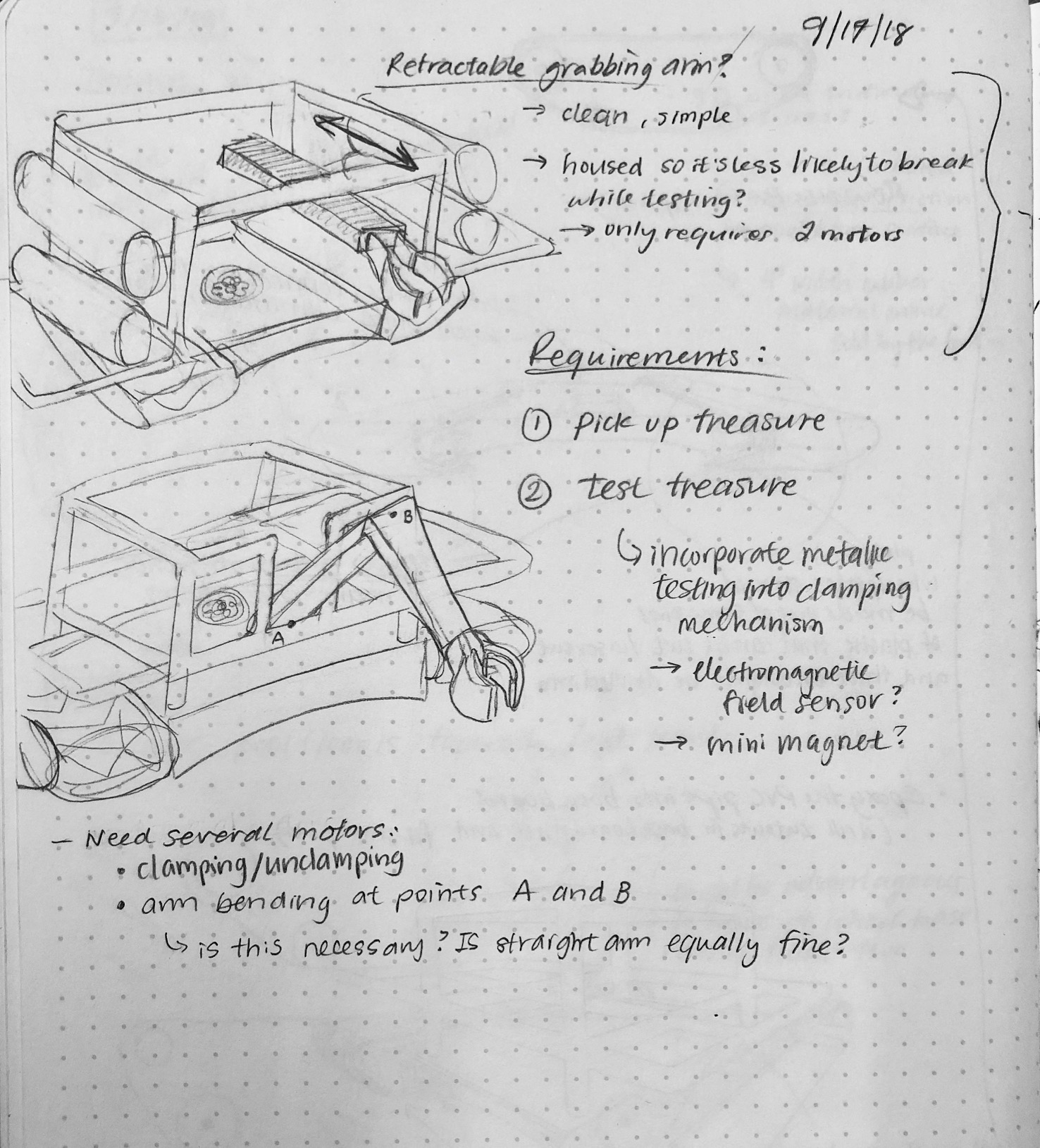
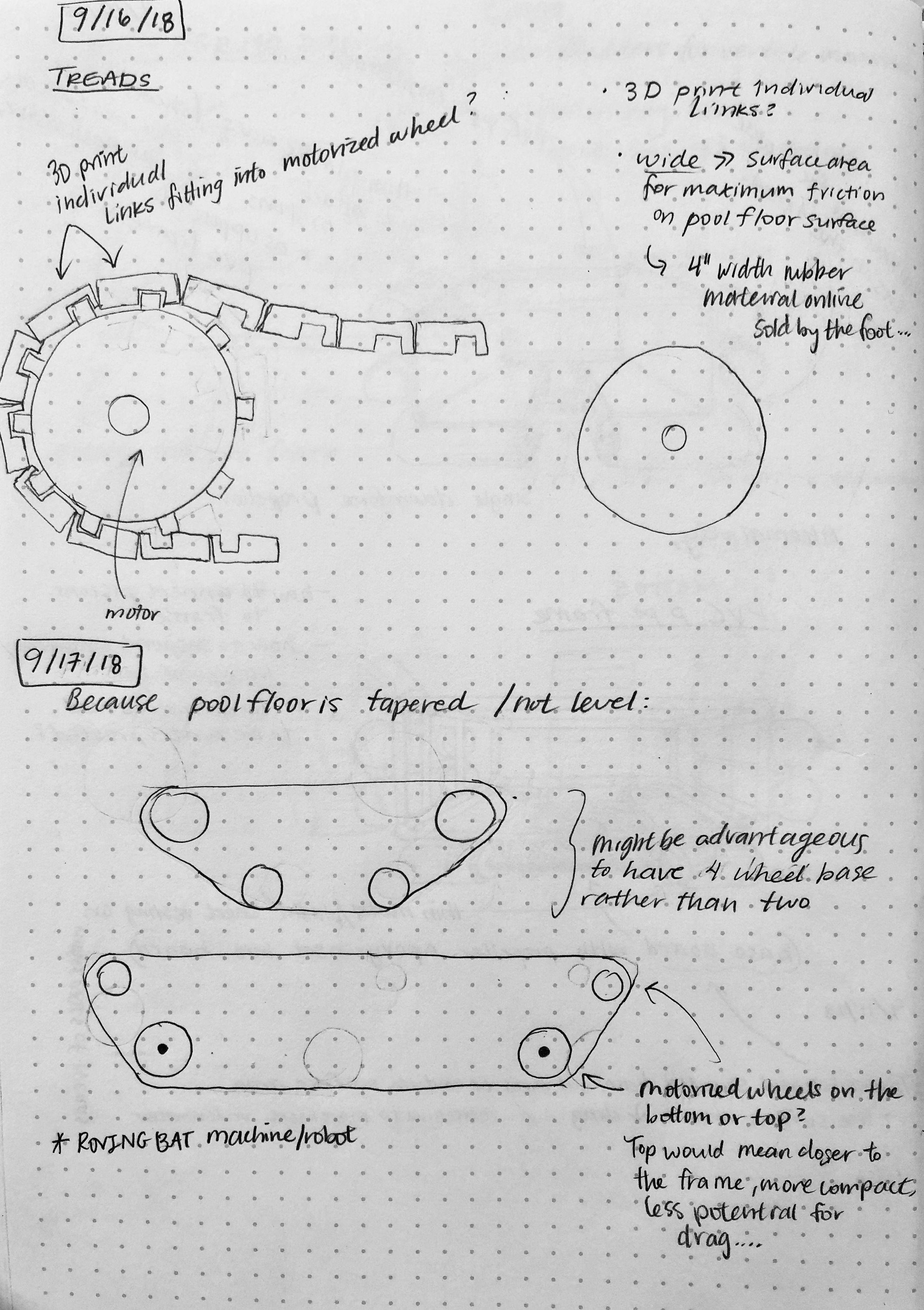
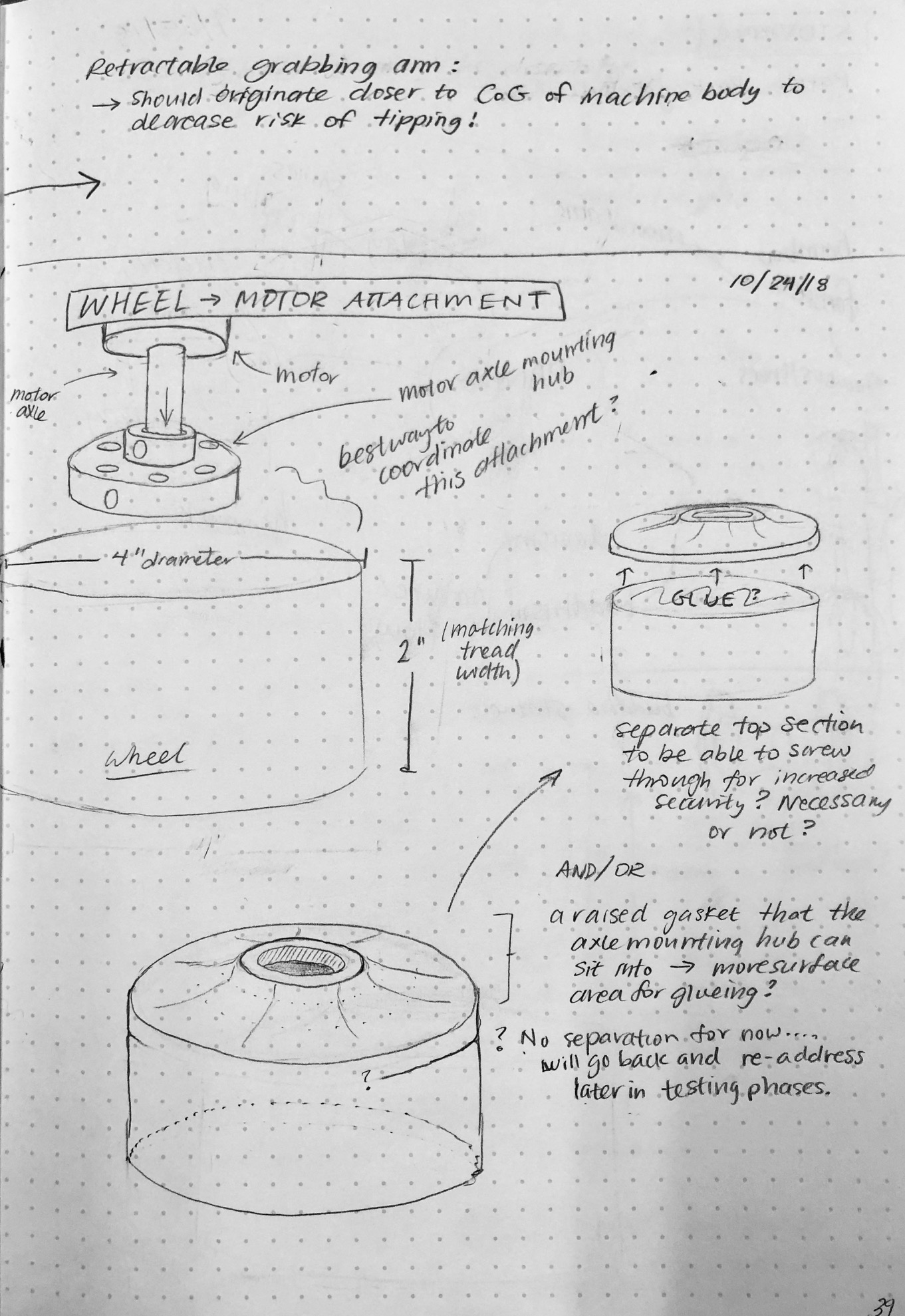
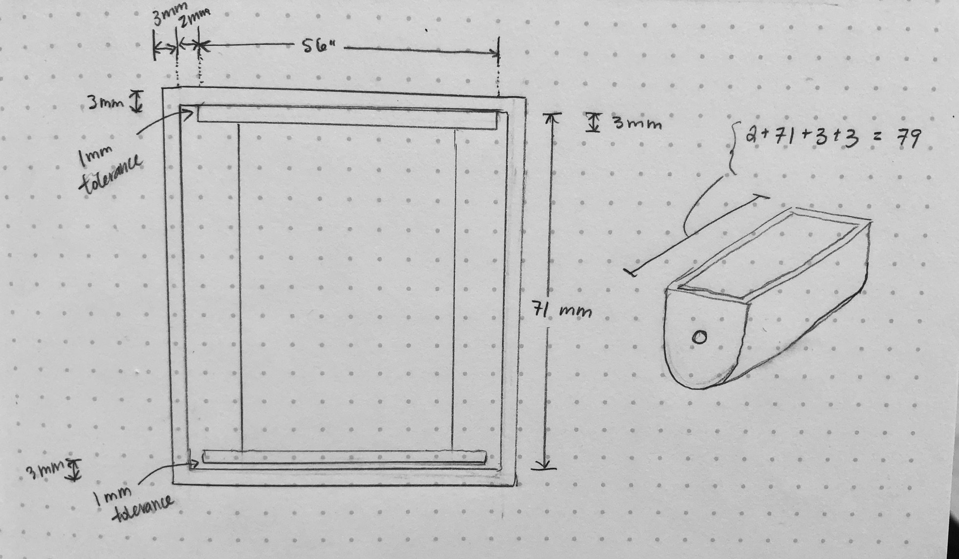
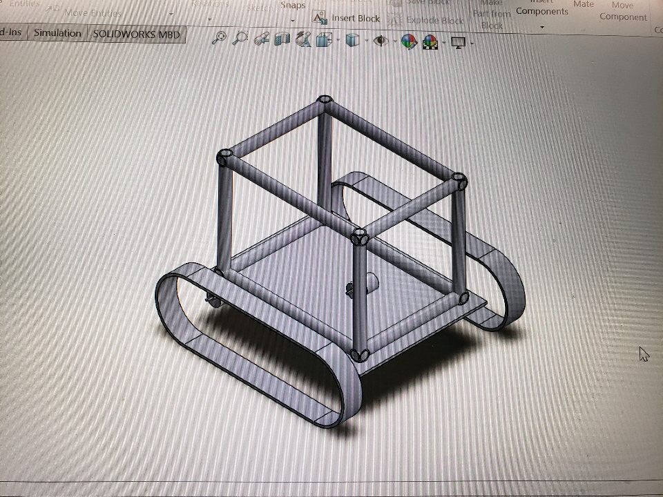
Below are some of my personal ideas for the frame, tread and wheel design, and potential arm design. I thoroughly enjoy the process of sketching and draw from my experience as an artist to create such sketches.
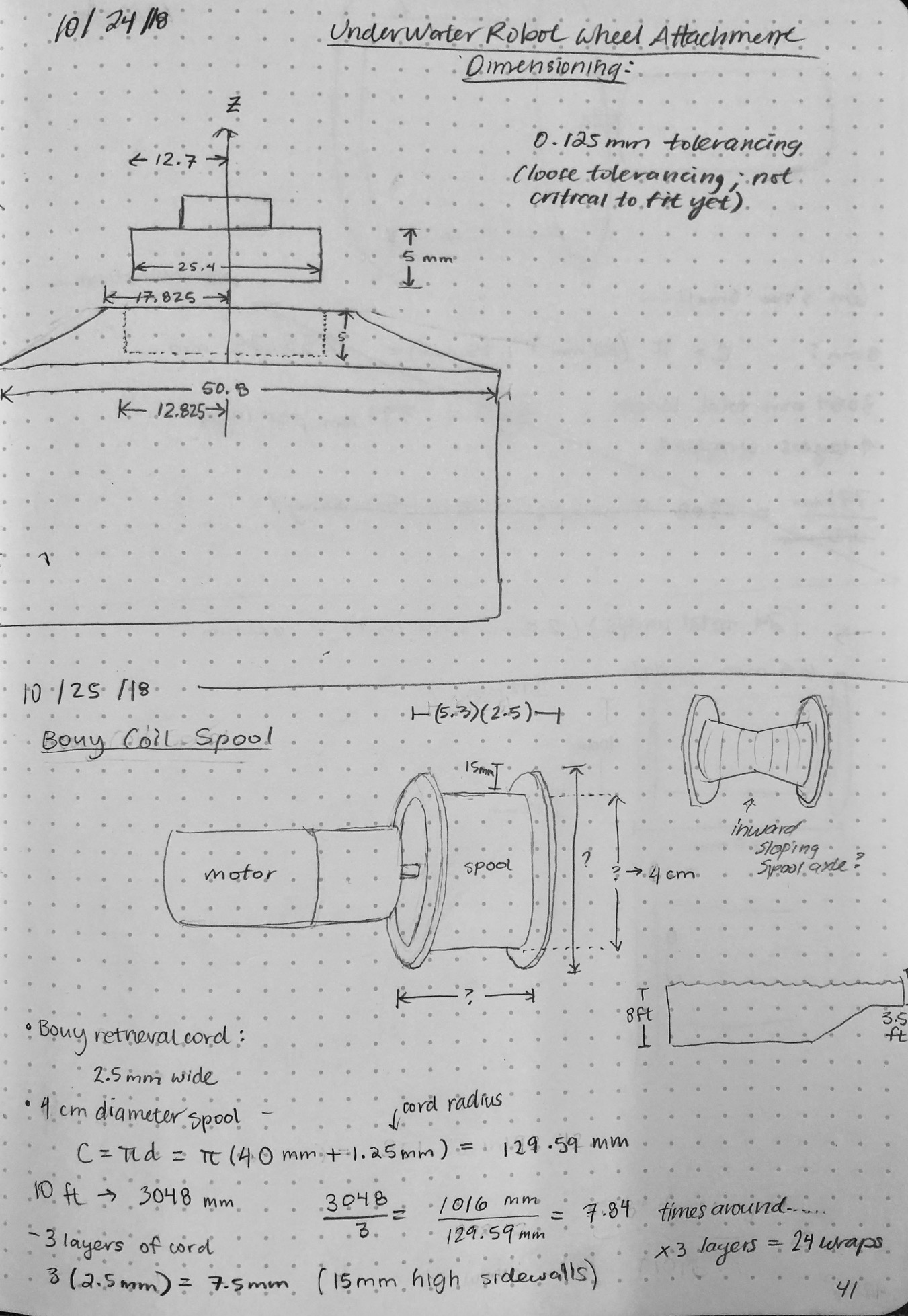
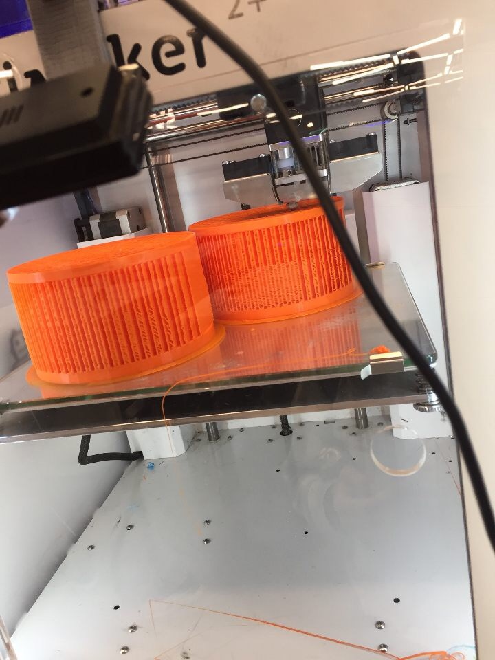
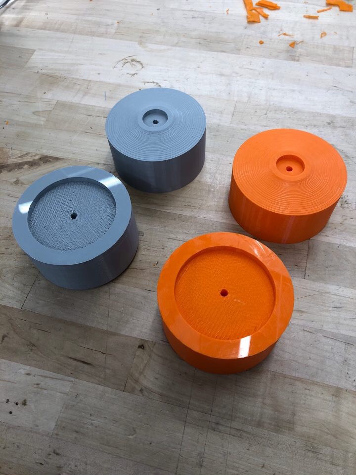
Here is a coiled spool which will serve to house the buoy cord when the buoy is in it’s initial position at the bottom of the pool:
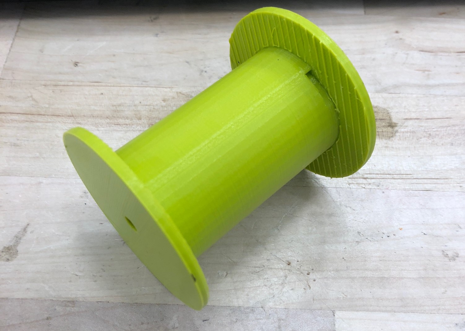
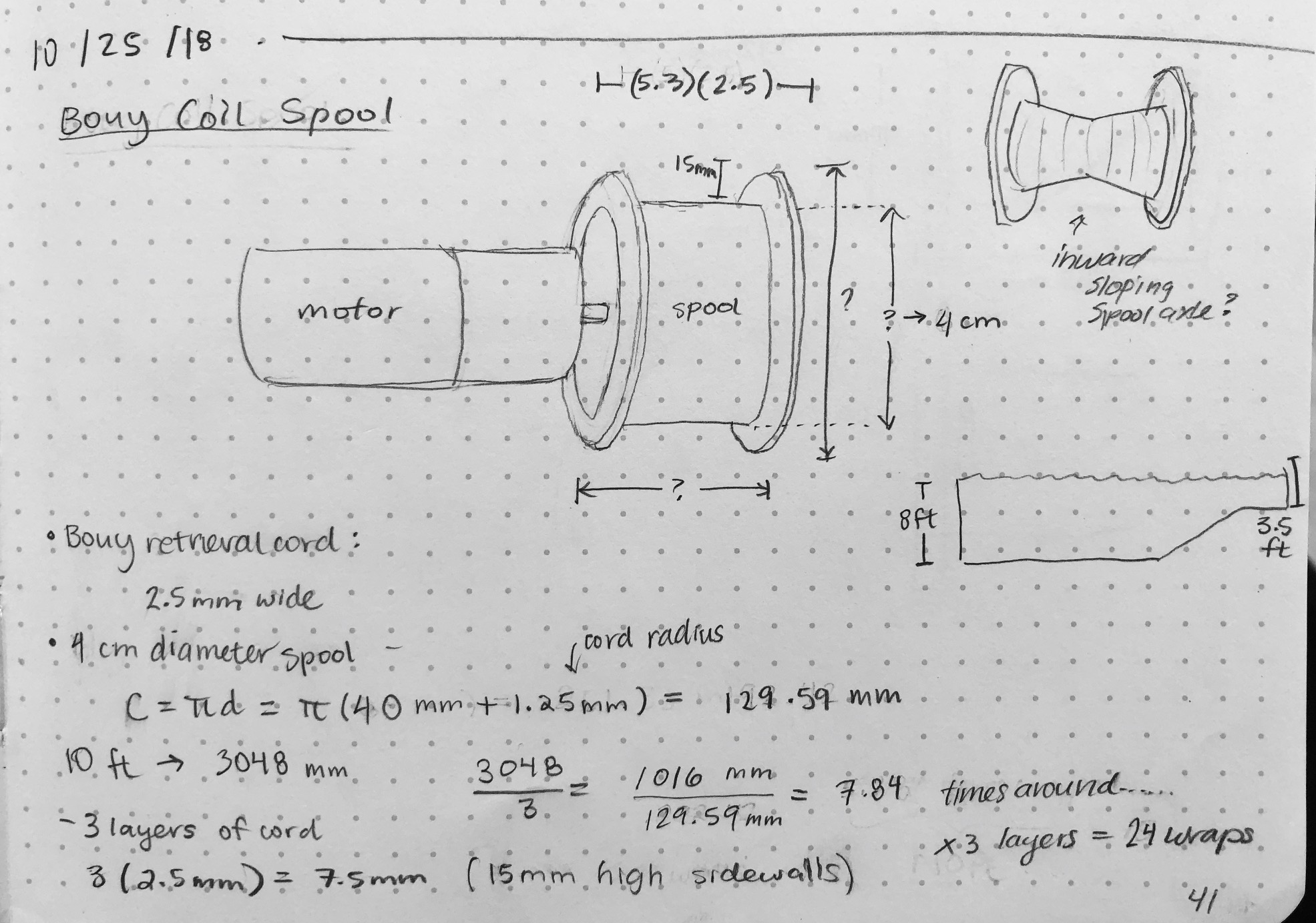
This spool will fit into a housing which will keep the cord within the bounds of the spool. Initially I had envisioned the cord should be made out of a stiff think gauge wire in order to maintain steadiness of the buoy. However, we learned through testing that such a cord did not coil well within the 3D printed housing, as its natural coil diameter is far larger than that of the housing. Heavy duty fishing line ended up doing the trick though!
After several attempts with a rubber tread without much success due to tread slippage to one side or another, and insufficient contact with the pool floor, we opted to change the design.
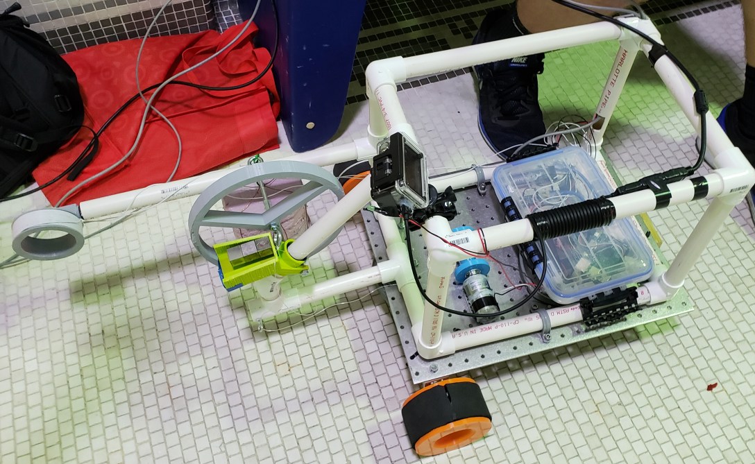
I sketched, modeled and 3D printed several wheels to accommodate the new design, which had two front wheels and one free wheel in the center back.
To detect the metal ‘treasure’, I had the idea of placing a strong magnet on a somewhat level surface which could be brought near each object to see whether not it is attracted. The magnet would either have no effect (near the plastic and aluminum objects) or stick to the object allowing the robot to maneuver without being attached to the magnet. The sensor arm is made up of a coil of wires, essentially a wide inductor. A small LED if the magnetic flux induced by the sensor is affected by the presence of either metal object.
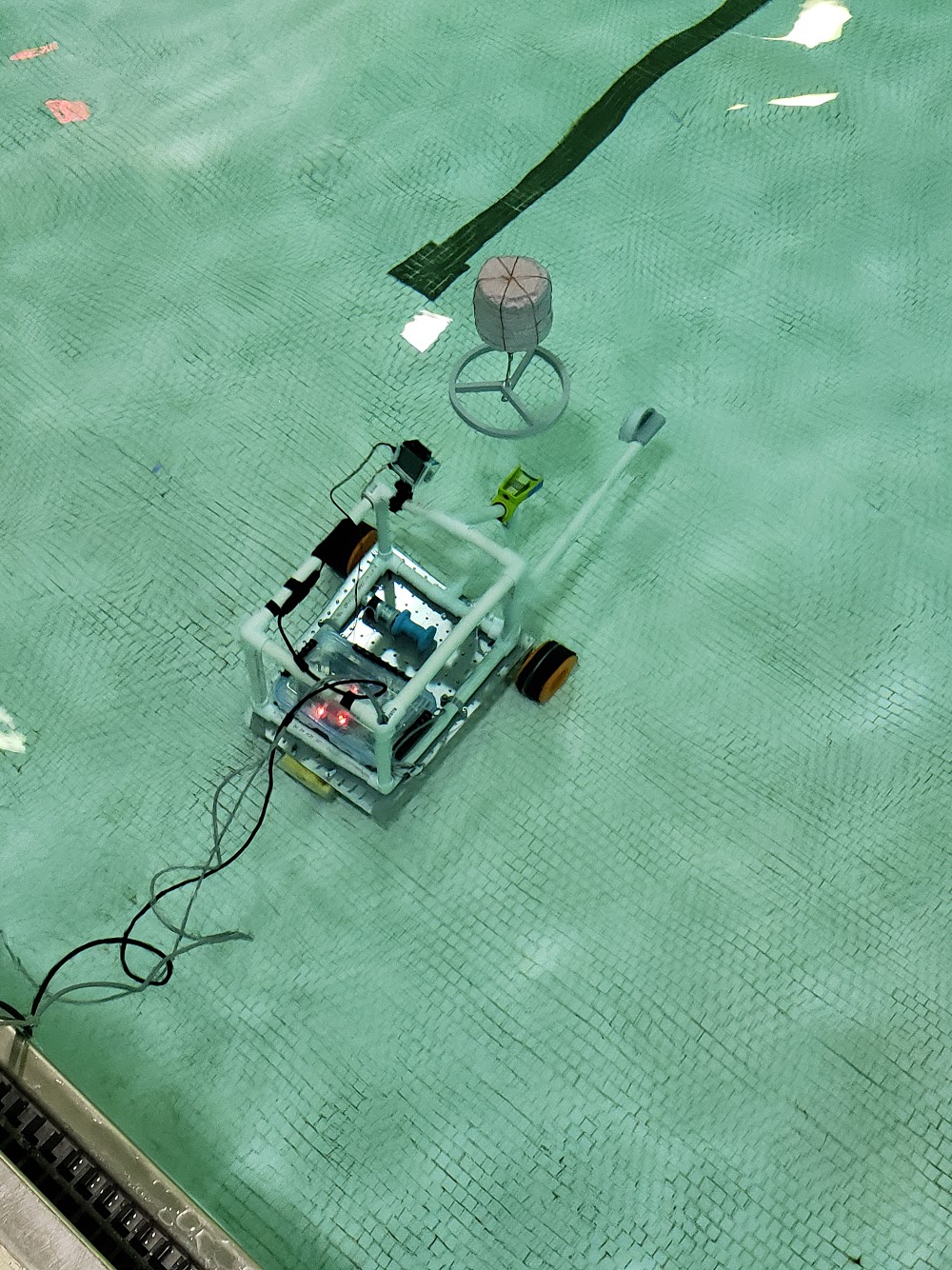
Once the identity of each object is determined, we can maneuver the robot so that the circular grey capture is underneath one of the treasure’s hooks. Releasing the spool allows the treasure to be caught and rise to the surface of the pool.
Each of our team contributed to the CAD model, and I created the final assembly in SolidWorks. The image below is representative of the final design after many cycles through the design and prototyping process:
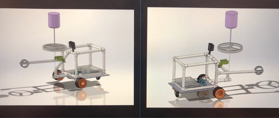
In final testing, our team’s robot performed the best out of four teams. Our designed proved to be the most accurate, as well as most time efficient and consistent.